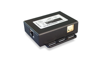
Together with the Nickl ImageCutter30, the ImageHub30-DC001 is able to put images to the dashboard display of various vehicles. The ImageHub30-DC001 gets its signal from the ImageCutter, which has already tailored the signal timing to the needs of the specific car interface. The ImageHub30 does the physical adaption. For savety purposes, the original image can be displayed alternatively. E.g. safety-relevant information can be displayed at critical situations.
The supply of the very compact Nickl ImageHub30-DC001 comes from the ImageCutter30, easing the integration into the target car.
Transmission of the signals between the ImageCutter and the ImageHub is done via standard patch cables known from the network technique. By AC coupling, a DC decoupling of the ImageCutter and ImageHub is achieved, allowing potential differences which may be present between the front and the rear area of the wiring harness.
|
|
| Particular features |
- Multiplexing between original image and PC/Video image
- DC De-coupling of ImageHub30 and ImageCutter30
- Obtains supply from ImageCutter30
|
|
| Order Data: |
1EMIH30-DC001 |
Please select und confirm for more informations.
|
|
|
Documentation:
|
|
Data Sheet
|
|
|
|
|
Configuration file:
|
|
VTI Config file
|
|
|
|
|
Tool for configuration:
|
|
VTI tool
|
|
|
Installation guidelines VTI tool
To configure the ImageHub30 for a specific type of car, follow the steps below:
- Make sure that the ImageHub30 is connected to the ImageCutter30 and that the ImageCutter is provided with power supply.
- Connect the RS-232 interface of the ImageCutter30 with the RS-232 port of your PC.
- Download and extract the files of the Zip-Archive and start the configuration tool VtiConfig.exe
- Under Communication, select the COM port where the ImageCutter30 is connected to
- Download the configuration file for the appropriate type of car. Please make sure that you have the fitting variant of ImageHub30. The configuration file can be found in the car-specific description, which is listed in the compatibility list.
- Load the configuration file with the Load/Save button
- At the Communication tab, press the Button Write to VTI.
For more information to the VtiConfig tool, read the Manual of the VtiConfig tool which can be found in the Zip-Archive.
|
|

